Conveyor – Floating Unit
Floating Units are the solution for all processes that require non-contact transportation and precise positioning of flat, fragile objects.
Floating units are used for the structuring process in solar panel production. During the process, the glass substrate hovers above the Floating Unit at a defined distance of a few μm from the carrier plate.
Description
Concept and Design
Floating Units are the solution for all processes that require non-contact transportation and precise positioning of flat, fragile objects.
Floating units are used for the structuring process in solar panel production. During the process, the glass substrate hovers above the Floating Unit at a defined distance of a few μm from the carrier plate.
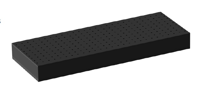
This is achieved through the precise arrangement of pressure nozzles and vacuum nozzles. The requirements for precise positioning could not be met by simply creating an air cushion by pressure nozzles that work against the ambient pressure. Only the interaction of positive and negative pressure makes it possible to position the glass substrates so precisely that they can be moved within the narrow focus of a stationary laser. The repeatability of flatness within defined positions on moving substrates is very high.
The body of the Floating Unit is made of black anodized aluminum.
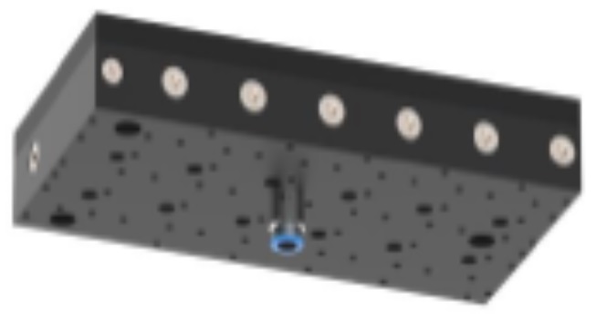
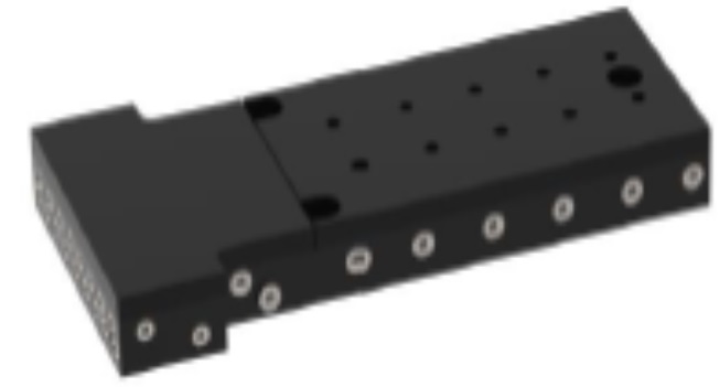
Side-by-side placement of several Floating Units is possible. Deviating sizes are available on request.
The air gap at the edges can be individually controlled by a separate air supply. It is set to 45 μm, while the PV functionality is retained.
key Futures
- Variable sizes possible
- Non-contact flattening and transport of substrate
- Substrate thickness 5 mm ± 0.5 mm
- Air bearing/vacuum chuck
- Nominal air gap 30 µm
- Clean room suitable
- Side-by-side placement is possible
Setup Procedure
Setup Procedure
- Connect the Floating Unit (FU) to 4 Tip-Tilt-Units (TTUs), which serve as a leveling
- Set TTUs to the approximate
- Position FU on the
- Connect to air supply and
- Align FU as required, using an auxiliary axis system and/or a digital spirit
- Continue setting up the 2nd FU:
Align 2nd FU with reference to 1st FU. Use an auxiliary axis system, a digital spirit level or a steel ruler. For optimum performance, the height offset at the gap between the FUs should be < 5 µm. - Continue with the setup of additional FUs as described
Specifications
Specifications
| Mechanical Data | Unit | PA | PV |
| Dimension (length x width x height) | mm | 153 x 300 x 35 1) | 200 x 432.5 x 50 1) |
| Mass | kg | 5.6 2) | 8.5 2) |
| Substrate thickness | mm | 2.5 ± 0.5 | |
| Max. acceptable glass flatness | µm | – | 70 µm / 200 mm |
| Nominal air gap | µm | ≥100 | 20 – 30 |
| Flatness of air gap over 100 mm | µm | – | ± 5 |
| Flatness of air gap over the entire Floating Unit | µm | – | ± 6 |
| Repeatability of air gap with moving glass at any reference point on the PV chuck | µm | ± 1 | |
| Flatness of chuck surface | µm | < 10 | |
| Air supply at PA zone | mbar | 50 | 50 |
| Air supply at PV zone | mbar | 1300 | |
| Vacuum | mbar g | – 600 | |
| Air consumption | Sl/min | 15 | 15 |
| Vacuum consumption | Sl/min | 25 | |
| Clean room suitability | suitable | suitable | |
| Material | aluminum, black anodized | ||
| MTBF | h | > 20,000 | > 20,000 |
| Requirements on Air Quality | Value | ISO class | |
| Particle size | ≤ 1 µm | DIN ISO 8573-1 – class 2 | |
| Pressure dew point | ≤ +3 °C | DIN ISO 8573-1 – class 4 | |
| Oil content | ≤ 0.1 mg/m³ | DIN ISO 8573-1 – class 2 | |
Documentation
Download / View Documentation
 Loading...