
Concave and Convex Mirrors and Lenses: Differences and Lab Uses Explained
When designing an optical train on a breadboard, choosing between concave and convex geometries dictates how your system manipulates wavefronts, balances aberrations, and handles optical power. While introductory physics treats these components as ideal ray-benders, working in a precision laboratory environment tells a very different story. A subtle miscalculation in surface orientation or conjugate ratio can ruin beam quality, induce severe spherical aberration, or misalign an entire laser cavity.
According to data from PhotonicsNL, the Dutch photonics cluster comprises over 300 active companies and research institutes. From the cleanrooms in Brainport Eindhoven to ultrafast laser setups at TU Delft and TNO, engineering teams rely daily on precise spherical optics selection to reach sub-micron tolerances. Whether you are assembling an optical inspection jig or designing high-power beam delivery, understanding the precise operational divergence between concave and convex surfaces—across both reflective mirrors and transmissive lenses—is the bedrock of dependable optical engineering.
| Optical Parameter | Concave Mirror | Concave Lens | Convex Lens | Convex Mirror |
|---|---|---|---|---|
| Primary Optical Action | Converging ($f > 0$) | Diverging ($f < 0$) | Converging ($f > 0$) | Diverging ($f < 0$) |
| Image Type Formed | Real (outside $f$) or Virtual (inside $f$) | Virtual only (for real objects) | Real (outside $f$) or Virtual (inside $f$) | Virtual only (for real objects) |
| Chromatic Dispersion | Zero (Pure reflection) | Present (Material dependent) | Present (Material dependent) | Zero (Pure reflection) |
| Common Lab Curvatures | Spherical, Parabolic, Ellipsoidal | Plano-concave, Bi-concave | Plano-convex, Bi-convex | Spherical, Parabolic |
| Primary Failure Risk | Spherical aberration at low f-numbers | Geometric aberrations at steep conjugates | Thermal lensing, spherical aberration | Beam expansion clipping aperture |
| Budget & Component Cost | Moderate to High (Coating dependent) | Low to Moderate | Low to Moderate | Moderate |
Understanding Curvature: Key Criteria for Evaluating Concave and Convex Optics
Before selecting hardware from an optics catalog, an engineer must assess four foundational performance criteria that govern curved optical surfaces.
Focal Length and Ray Convergence vs. Divergence
Under the standard Cartesian sign convention used in modern optical design software like Zemax or FRED, curvature signs directly determine the focal sign ($f$):
- Reflective systems: A concave mirror possesses a positive focal length, concentrating collimated incident rays toward a real focal spot. Conversely, a convex mirror has a negative focal length, causing parallel rays to diverge as if originating from a virtual point behind the reflective surface.
- Transmissive systems: A convex lens provides positive focal power, bending rays inward toward an optical axis via refractive index mismatches ($n_{text{glass}} > n_{text{medium}}$). A concave lens does the opposite, spreading light outward into a diverging cone.
Image Formation: Real vs. Virtual
Optical elements that produce real images allow physical sensors, spatial filters, or detector arrays to sit directly in the focal plane.
- Positive optics (concave mirrors and convex lenses) project real, inverted images whenever the object distance exceeds the focal length ($s_o > f$).
- Negative optics (convex mirrors and concave lenses) yield upright, demagnified, virtual images under real object illumination. These images cannot be captured directly on a projection screen without secondary relay optics.
Geometric Aberrations (Spherical Aberration and Coma)
Spherical surfaces are simple to manufacture to sub-nanometer surface roughness, but they do not focus light to a single, perfect point. Marginal rays entering the edge of a spherical optic experience greater refraction or reflection than paraxial rays near the center. This path length differential leads directly to spherical aberration. When light enters off-axis, asymmetry yields coma and astigmatism, degrading the wavefront error of your beam train.
Substrate and Coating Durability for High-Power Environments
Transmissive elements suffer from bulk absorption, which induces thermal lensing when irradiated with kilowatt-class continuous-wave (CW) or petawatt-class femtosecond pulses. High-power handling demands high-purity fused silica substrates with optimized anti-reflective (AR) coatings. Reflective optics, by contrast, depend entirely on thin-film dielectric stacks or enhanced metal layers (such as gold, silver, or protected aluminum) to maximize Laser-Induced Damage Thresholds (LIDT).
Concave Optics: Mechanics, Curvature Types, and Lab Applications
Concave surfaces curve inward, resembling a bowl or cavity. In optical design, the behavior of a concave boundary flips depending on whether light passes through it or bounces off it.
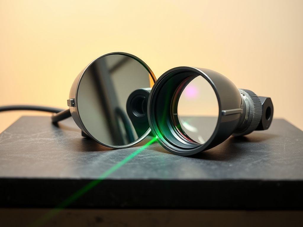
Concave Mirrors: Beam Convergence Without Dispersion
Because reflection relies strictly on the Law of Reflection ($theta_i = theta_r$) rather than Snell’s Law, a concave mirror serves as an achromatic optical focusing element. When focusing broad-spectrum light or sub-picosecond pulses, a concave mirror avoids the temporal pulse-broadening (group velocity dispersion) that transmissive lenses inevitably introduce.
In laser cavity designs, spherical concave mirrors are standard components used to form stable Fabry-Pérot resonators. By matching the mirror’s radius of curvature ($R$) to cavity length parameters, researchers can tightly control the beam waist ($w_0$) and ensure stable spatial mode profiles.
Concave Lenses: Beam Divergence and Image Reduction
A concave transmissive element acts as a negative lens. Parallel rays entering the surface diverge away from the optical axis. These elements are produced in two primary geometry formats:
- Plano-Concave: Featuring one flat surface and one inward-curved surface. As detailed in the optical design guides at the RP Photonics Encyclopedia, orienting the curved surface toward the infinite conjugate (the collimated beam) minimizes spherical aberration. High-quality plano-concave lenses are standard components used to expand laser beams or introduce negative focal length into optical trains.
- Bi-Concave: Featuring two symmetrical inward curvatures. Symmetrical custom bi-concave lenses are engineered for applications where input and output beams diverge or converge symmetrically (conjugate ratios close to 1:1).
Plano-Concave Lens:          Bi-Concave Lens:
     | (                          ) (
     |  (                        (   )
     |   (                      (     )
     |    )                    (       )
     |   (                      (     )
     |  (                        (   )
     | (                          ) (
Flat   Curved               Curved   Curved
Laboratory Use Cases
- Laser Beam Expanders (Galilean Configuration): Placing a plano-concave lens ahead of a positive lens creates a compact beam expander that avoids an internal focal point. This configuration prevents the dielectric breakdown of air, which often occurs inside high-energy pulsed systems.
- Spectrometer Focusing: Concave diffraction gratings and mirrors focus multi-wavelength spectra onto linear detector arrays without requiring color-correcting doublet optics.
- Optical Cavities: Dutch quantum research setups frequently leverage ultra-high-reflectance concave dielectric mirrors to build high-finesse optical cavities that trap single photons.
Convex Optics: Mechanics, Curvature Types, and Lab Applications
Convex surfaces bulge outward toward the incoming light. They represent the primary engine for image capture and light gathering across the photonics sector.
Convex Lenses: Positive Focusing and Magnification
When a collimated light wavefront passes through a convex glass surface, the center of the beam is delayed relative to the margins because the glass is thicker in the middle. This physical phase delay transforms a planar wavefront into a converging spherical wavefront.
- Plano-Convex: The industry workhorse for focusing collimated beams down to diffraction-limited spot sizes. High-grade plano-convex lenses perform best when the curved surface faces the incoming parallel beam, splitting refraction evenly across both surfaces to reduce geometric distortion.
- Bi-Convex: Best applied when light converges on one side and diverges on the other under similar conjugate distances, such as 1:1 relay imaging setups.
Convex Mirrors: Field-of-View Expansion and Attenuation
A convex mirror rapidly diverges incoming rays, producing an upright, virtual image positioned behind the mirror plane. In laboratory settings, convex mirrors serve as clean, dispersion-free beam attenuators or beam expanders within reflective telescope systems (such as the secondary mirror in a Cassegrain configuration). Because they disperse energy over a widening spatial area, they drastically reduce energy density downstream.
Laboratory Use Cases
- Fiber Coupling: Injecting a free-space laser beam into a single-mode fiber with a 5 µm core demands high numerical aperture (NA) convex optics. Laboratories often use precision-ground customer-specific plano-convex lenses with performance-matched anti-reflective coatings to maximize coupling efficiency.
- Collimation Tubes: Placing an emission source (such as an LED, laser diode, or fiber tip) exactly one focal length away from a convex lens outputs a parallel, low-divergence beam across the table.
- Machine Vision and Inspection: Convex imaging assemblies form the optical front-ends for automated optical inspection (AOI) setups monitoring semiconductor processing lines.
Head-to-Head Comparison: Concave vs Convex Optical Elements
Selecting the right component requires matching system constraints—such as bandwidth, space, and optical power—against the specific geometry of the optic.
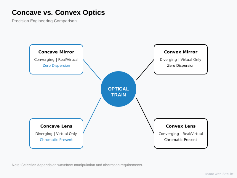
Infographic by SiteLift
At-a-Glance Optical Comparison Matrix
| Application Goal | Preferred Optic Type | Why This Specific Optic Wins | Trade-Off to Manage |
|---|---|---|---|
| Broadband Ultrafast Focusing | Concave Mirror | Completely eliminates chromatic dispersion and pulse broadening. | Off-axis alignment introduces coma; requires careful tilt control. |
| Compact Laser Beam Expansion | Plano-Concave Lens | Generates a virtual focus, eliminating air breakdown at high pulse energies. | Introduces chromatic aberration if multi-line lasers are used. |
| Fiber Injection / Coupling | Plano-Convex Lens | High optical power in a compact mechanical profile; easy to align. | Back-reflections require AR coating to prevent laser diode instability. |
| Wide-Angle Beam Sampling | Convex Mirror | Diverges and attenuates high-power beams across a wide field of view. | Produces a virtual focal point; cannot capture light onto a sensor directly. |
Transmission vs. Reflection: Mirrors vs. Lenses Breakdown
The debate between transmissive lenses and reflective mirrors hinges on operational bandwidth and physical layout:
- Chromatic Aberration: Lenses rely on refractive index values ($n$), which vary across wavelengths according to Sellmeier equations. This chromatic dispersion forces broadband systems to rely on complex multi-element achromatic doublets. Mirrors reflect light at the boundary, making their focal lengths entirely independent of wavelength.
- Physical Footprint and In-Line Geometry: Transmissive lenses maintain a straight optical axis, simplifying rail alignment. Mirrors require folded optical paths, often operating off-axis (such as Off-Axis Parabolic, or OAP, mirrors). While folded paths complicate alignment, they shrink the physical footprint of industrial instruments.
- Power Handling (LIDT): In pulsed laser processing, bulk substrate impurities can cause catastrophic breakdown inside transmissive lenses. High-quality dielectric mirrors distribute electric field stress across alternating thin-film layers, yielding significantly higher damage thresholds.
Why Curved Mirrors Are Consistently Underrated in Custom Labs
Our editorial view: Too many lab technicians default to ordering transmissive lenses because on-axis alignment on an optical rail seems straightforward. However, transmissive trains inevitably accumulate surface reflection losses, chromatic blur, and thermal drift over time.
If you are dealing with ultrafast femtosecond pulses or wide spectral bands, mastering off-axis concave mirrors early in the prototyping phase eliminates dispersion correction steps downstream. The initial mechanical alignment takes longer, but the resulting optical throughput and pulse fidelity are well worth the effort.
Engineering Decision Guide: Spherical Optics Selection for R&D and Industrial Labs
Optimizing an optical train requires balancing geometric performance against practical mechanical constraints.
Is your light broadband / ultrafast?
├── YES ──> Choose REFLECTIVE optics (Concave/Convex Mirrors)
└── NO (Monochromatic / CW) ──> Continue below:

Do you need to CONVERGE or DIVERGE the beam?
├── CONVERGE ──> Plano-Convex Lens (Infinite conjugate: flat face toward focus)
└── DIVERGE  ──> Plano-Concave Lens (Beam Expander: curved face toward incoming beam)
Matching Lens Curvature Types to Conjugate Ratios
Spherical aberration scales non-linearly with the bending factor of the optic. To minimize wavefront distortion, match the lens shape to your system’s conjugate ratio ($C = S_2 / S_1$):
- Infinite Conjugate Systems ($C to infty$ or $0$): When focusing a collimated beam to a point, or collimating a point source, choose a plano-convex or plano-concave lens. Always face the curved surface toward the parallel (infinite conjugate) beam path.
- Finite Conjugate Systems ($C approx 1$): When imaging an object onto a sensor at near-unit magnification, use a bi-convex or bi-concave optic. Symmetrical curves divide refraction evenly between the entrance and exit surfaces, suppressing spherical aberration.
Alignment and Mounting Best Practices
High-precision optics can be warped by improper mechanical clamping. According to technical resources published by SPIE, mechanical stress from overtightened retaining rings can warp precision surfaces and ruin system wavefronts.
Furthermore, research published in Applied Optics by Optica demonstrates that surface form error in spherical optics can degrade wavefront precision by up to 25% if mounting stress is not properly managed.
Pro Tip: Always employ torque-limiting drivers when securing optics inside threaded retention cells. Use three-point kinematic mounts for curved mirrors and compliant O-rings or Delrin washers for transmissive lenses to prevent mechanical stress birefringence.
Pro Tip: When aligning a plano-concave lens in a high-energy laser beam expander, verify that the planar surface is tipped by 0.5° to 1° relative to the incident optical axis. This minor tilt diverts ghost back-reflections away from the laser cavity, preventing catastrophic parasitic oscillation and optical damage.
Sourcing and Integration in the Dutch Photonics Ecosystem
The European photonics market accounts for over €50 billion annually, with high demand driven by precision optics and optical manufacturing, according to the European Photonics Industry Consortium (EPIC).
Within the Netherlands, this demand is concentrated in demanding applications—from deep-ultraviolet (DUV) and extreme-ultraviolet (EUV) lithography systems in Veldhoven to integrated photonics testing benches in Enschede and Eindhoven. Meeting these industrial tolerances requires optical components with verified surface figure accuracies (typically $lambda/10$ to $lambda/20$ peak-to-valley), scratch-dig specifications of 10-5 or better, and certified LIDT ratings.
Precision Photonics Solutions with Te Lintelo Systems
Building complex optical systems requires more than off-the-shelf components; it demands deep engineering expertise and dependable component validation. Since 1985, Te Lintelo Systems (TLS) has served as an essential partner to research centers, high-tech OEM builders, and laser laboratories throughout the Netherlands and across Europe.
Whether you need specialized substrate materials like UV-grade fused silica, calcium fluoride, or zinc selenide, or require custom dielectric coatings designed for high LIDT environments, TLS bridges the gap between design theory and laboratory implementation. Our team can help you select, customize, and integrate the ideal concave and convex mirrors and lenses for your next photonics project.
— tlsbv.nl
Frequently Asked Questions
What is the main functional difference between a concave and convex lens?
A convex lens is a positive, converging element that bends incoming parallel light rays inward toward a real focal point. It is thicker at its center than at its edges. A concave lens is a negative, diverging element that is thinner at its center, bending parallel rays outward as if they originated from a virtual focal point behind the lens.
Why does a concave mirror converge light while a concave lens diverges light?
A concave mirror uses reflection: light bounces off its inward-curved surface back toward the incoming medium, which angles marginal rays inward toward a common, real focal point. A concave lens uses transmission: light passes through the glass, where refractive index differences cause rays to refract away from the thicker outer edges, resulting in a diverging beam.
When should a lab engineer choose a curved mirror over a curved lens?
Curved mirrors are preferred when working with broadband light sources, ultra-short femtosecond laser pulses, or high-energy beams. Because mirrors reflect light at their surface, they introduce zero chromatic aberration, zero pulse dispersion, and avoid the bulk material absorption and thermal lensing common to transmissive lenses.
How does conjugate ratio determine whether to use a plano-convex or bi-convex lens?
The conjugate ratio ($S_2 / S_1$) compares the object distance to the image distance. When dealing with an infinite conjugate system (such as focusing a collimated laser beam or collimating an emission source), a plano-convex lens minimizes spherical aberration when its curved face points toward the parallel beam. When the system operates close to a 1:1 ratio (where object and image distances are roughly equal), a symmetrical bi-convex lens splits refraction evenly across both surfaces, yielding superior wavefront performance.