
Fiber Laser Technology: How It Works and Where Dutch Manufacturing Uses It
Over the past two decades, the industrial cutting table and welding cell have undergone a quiet revolution. If you walk through a sheet metal shop in Brabant or visit an OEM integration bay in Twente, the hum of gas-discharge tubes has largely disappeared. In their place sits the fiber laser—a compact, solid-state powerhouse that generates coherent light directly within glass fibers thinner than a human hair.
Today, this solid-state architecture defines modern laser material processing. Across the European Union, photonics has evolved from a niche discipline into a bedrock technology. According to Photonics21, the European photonics industry accounts for over €50 billion in annual revenue, with laser material processing representing a key growth pillar. Within the Netherlands, where micro-machining tolerances dictate the success of global lithography systems and food processing machinery demands clean, sanitary welds, understanding how a modern fiber laser source operates is essential for maintaining a competitive manufacturing edge.
What Is a Fiber Laser and How Does It Work?
At its core, a fiber laser is a solid-state device where an active optical fiber, doped with rare-earth ions, serves as the gain medium. Unlike traditional gas or rod-based lasers, light generation, amplification, and delivery all happen inside a flexible optical waveguide.
+---------------------------------------------------------------------------------+
|                           FIBER LASER ARCHITECTURE                              |
|                                                                                 |
|  +--------------------+     Coupler / Combiner     +-------------------------+  |
|  | Pump Diode Modules | ===> [ ]==================>| Cladding                |  |
|  +--------------------+      |                     |   +------------------+  |  |
|                              |  HR-FBG             |   | Doped Core (Yb)  |  |  |
|  +--------------------+      |  |                  |   +------------------+  |  |
|  | Pump Diode Modules | ===> [ ]|                  | Cladding                |  |
|  +--------------------+         |                  +-------------------------+  |
|                                 |                               |               |
|                                 v                               v  OC-FBG       |
|                       High-Reflector FBG             Output Coupler FBG         |
|                                                                 |               |
|                                                                 v               |
|                                                     Collimated Laser Beam       |
+---------------------------------------------------------------------------------+
The Role of Rare-Earth Dopants: The Ytterbium Fiber Laser
The heart of an industrial cutting or welding laser is the ytterbium fiber laser. Silica glass ($SiO_2$) on its own cannot create laser light; it must be chemically treated—or “doped”—with rare-earth elements.
Ytterbium ($Yb^{3+}$) is the dopant of choice for heavy industrial applications because of its simple electronic energy-level structure. When pump energy excites ytterbium ions, they absorb light in the 915 nm to 976 nm band and emit photons at wavelengths between 1030 nm and 1080 nm (most commonly centered around 1064 nm to 1070 nm).
This 1-micron wavelength offers a significant mechanical advantage: metals such as carbon steel, stainless steel, brass, and aluminium absorb 1-micron light at rates far higher than the 10.6-micron light produced by legacy $CO_2$ lasers. Because the energy levels in ytterbium are closely spaced, the quantum defect—the energy lost as heat during the conversion process—is exceptionally low. This thermal efficiency keeps the active core cool and allows systems to scale up to tens of kilowatts without optical distortion.
Optical Pumping and Resonant Amplification
To generate light inside the fiber, engineers use a double-clad architecture:
- The Inner Core: A narrow central channel (often 10 to 50 microns in diameter) doped with ytterbium ions.
- The Inner Cladding: A larger, undoped glass layer with a lower refractive index that surrounds the core.
- The Outer Cladding: A protective polymer or glass jacket with an even lower refractive index.
High-power semiconductor diodes inject multimode “pump” light directly into the inner cladding. As this pump light bounces internally along the fiber, it repeatedly crosses through the central doped core. The ytterbium ions absorb these pump photons and enter an excited energy state.
When a spontaneously emitted photon travels along the core, it triggers stimulated emission: the excited ions drop back to their base energy state, releasing new photons identical in phase, wavelength, and direction. The light amplifies continuously as it travels through the active fiber length.
Fiber Lasers vs. Conventional CO2 and Solid-State Systems
For decades, the standard choice for plate cutting was the radio-frequency excited $CO_2$ laser. While reliable, $CO_2$ systems struggle with high electrical consumption, complex mirror alignment, and massive gas consumption.
Data from Fraunhofer ILT indicates modern industrial fiber lasers achieve electrical-to-optical wall-plug efficiencies of 35% to 50%, compared to 8% to 12% for typical industrial $CO_2$ lasers. That jump translates directly into lower factory utility bills and smaller floor footprints.
| Performance Metric | Industrial Fiber Laser | Legacy $CO_2$ Gas Laser | Flashlamp-Pumped Nd:YAG |
|---|---|---|---|
| Operating Wavelength | ~1.07 µm (1070 nm) | 10.6 µm (10,600 nm) | 1.06 µm (1064 nm) |
| Wall-Plug Efficiency | 35% – 50% | 8% – 12% | 1% – 3% |
| Beam Delivery Method | Flexible silica fiber cable | Free-space external mirrors | Articulated arm or thick fiber |
| Maintenance Intervals | > 50,000 hours (diodes) | Frequent optics cleaning/gas refill | Lamp replacements every 500–1,000 hrs |
| Absorption in Metals | High (especially copper & brass) | Low (reflective in non-ferrous) | High |
| Footprint per kW | Compact, rack-mountable | Bulky resonator footprint | Medium to large floor unit |
Inside the Fiber Laser Source: Core Architectural Components
To appreciate why a modern fiber laser source can run uninterrupted for tens of thousands of hours, you have to look past the cabinet sheet metal and examine the components inside.
       +-----------------------------------------------------------+
       |             FIBER BRAGG GRATING (FBG) REFLECTION          |
       +-----------------------------------------------------------+

       Broadband Input Light ===> [ | | | | | | | ] ===> Transmitted Non-Resonant
                                  Periodic Refractive    Wavelengths
                                     Index Gratings
                                         ||
                                         /
                            Reflected Resonant Wavelength
                              (Forms In-Fiber Cavity Mirror)
Semiconductor Diode Pump Modules
The engine of any fiber system is its bank of gallium arsenide (GaAs) semiconductor diodes. Instead of relying on a single, ultra-high-power emitter that risks taking down the entire machine if it fails, modern sources combine multiple low-power, single-emitter diodes.
These single-emitters deliver high reliability, with mean-time-between-failure (MTBF) ratings often running above 100,000 hours. The pump modules couple light into intermediate fibers, which are then fused together using a tapered fiber bundle (combiner) that routes pump energy directly into the active double-clad fiber. Even if an individual diode degrades, the laser controller can adjust the drive current across remaining diodes to keep output power stable.
Fiber Bragg Gratings (FBGs) as Resonator Mirrors
Traditional solid-state lasers bounce light between two aligned glass mirrors across an open cavity. These mirrors require precise mechanical mounts and are vulnerable to vibration, thermal expansion, and airborne dust.
Fiber lasers replace those external mirrors with Fiber Bragg Gratings (FBGs). An FBG is a microscopic, periodic modulation of the refractive index etched directly into the silica core using high-intensity ultraviolet light:
- The High Reflector (HR-FBG): Acts as a near-perfect mirror, reflecting over 99.9% of light at the design wavelength.
- The Output Coupler (OC-FBG): Reflects a precise percentage (typically 5% to 15%) back into the cavity to sustain stimulated emission while allowing the rest of the light to exit.
Because these mirrors are physically part of the fiber itself, the resonator cannot go out of alignment. Thermal shock, factory floor vibrations from stamping presses, and transport shifts will not alter the laser cavity’s optical geometry.
Beam Delivery Fibers and Optical Quality (M² Factor)
Once light leaves the resonator, it passes through a feeding fiber into a delivery fiber via an optical combiner or splice. The physical properties of this delivery fiber govern the machine’s processing capabilities:
- Single-Mode Fibers ($M^2 < 1.3$): Single-mode systems use a very small core diameter (typically under 14 microns). The Beam Parameter Product ($BPP$) remains small, allowing the beam to focus down to a tight, high-energy focal spot. This configuration is ideal for fine micromachining, scribing silicon wafers, and high-speed cutting of thin sheet metal. For high-precision single-mode pulses, systems like the JenLas® fiber ns 50 single mode provide the beam control and pointing stability required for sub-millimeter tolerances.
- Multi-Mode Fibers ($M^2 > 2.0$): Multi-mode systems rely on larger cores (50, 100, or 200 microns). While their absolute focusability is broader, the energy profile across the spot shifts from a Gaussian peak toward a flat-top (top-hat) distribution. This wider profile is well-suited for thick plate cutting and laser welding, where a wider kerf and smoother heat distribution prevent spatter.
Pro Tip: When selecting a delivery core diameter, do not assume smaller is always better. While a low $M^2$ factor cuts thin foils quickly, cutting 15 mm stainless steel demands a broader beam kerf to allow assist gas to evacuate molten slag cleanly.
Laser Material Processing: Primary Industrial Applications
The physics of 1-micron light directly shapes how systems interact with various engineering materials. Modern automated manufacturing relies on fiber sources for three primary tasks: cutting, joining, and surface conditioning.
High-Speed Precision Sheet Metal Cutting
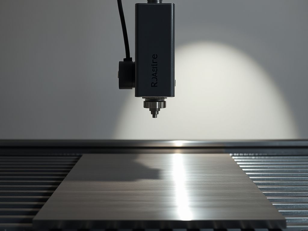
Laser cutting accounts for the largest installed share of high-power industrial fiber sources. The beam focuses onto the metal surface, heating it to its melting or vaporization temperature within milliseconds, while a coaxial assist gas blows the molten liquid out of the bottom of the kerf.
       LASER BEAM FOCUS DYNAMICS

       Laser Energy IN ===>         /  <=== Focusing Optics
                                   /
                                  /
                                | |     <=== Rayleigh Length (Depth of Focus)
                               /            Minimum Spot Diameter (d0)
                              /
       Material Surface =====[=======]=====
                             | Kerf  |  <=== Assist Gas Flow (N2, O2, Air)
                             | Slag  |
                             _______/
- Nitrogen Cutting (Fusion Cutting): The assist gas consists of high-pressure nitrogen (15 to 25 bar). The nitrogen provides no chemical heat; it mechanically purges molten material while keeping the cut edge inert. The result is an oxide-free edge ready for powder coating or welding without mechanical deburring.
- Oxygen Cutting (Flame Cutting): Used for thick carbon steel plates. The oxygen reacts exothermically with iron, releasing additional energy that speeds up the cut. While economical with low gas pressures, it leaves a thin iron oxide layer on the kerf walls.
- Reflective Non-Ferrous Metals: Pure copper, brass, and bronze were historically difficult to process with $CO_2$ lasers because the material reflected up to 95% of incoming 10.6-micron light back into the optics. Ytterbium fiber lasers operate at roughly 1.07 microns, where copper absorption is significantly higher. Paired with modern back-reflection isolators, fabricators can process copper busbars, brass shims, and high-conductivity heat sinks without damaging the optical cavity.
Deep-Penetration and Wobble Laser Welding
Laser welding works across two distinct thermodynamic regimes: conduction-mode welding and deep-penetration keyhole welding.
In keyhole mode, laser power densities exceed $10^6 text{ W/cm}^2$. The metal vaporizes immediately, creating a vapor-filled capillary (the keyhole) that traps laser light via multiple internal reflections. This process yields deep, narrow weld seams with narrow Heat-Affected Zones (HAZ), reducing part distortion.
              WOBBLE WELDING BEAM PATH PATTERNS

       Transverse Oscillation         Circular Wobble
              (Zig-Zag)                   (Spiral)
           /    /    /               @@@@@@@
          /    /    /               @  ---  @
         /    /    /                 @@@@@@@

       -> Bridges Wide Root Gaps    -> Homogenizes Melt Pool
       -> Smoothes Cap Appearance   -> Reduces Porosity in Al/Cu
High-power continuous systems—such as the JenLas® fiber cw 400—are widely used in precision component joining, medical instruments, and electrical subassemblies.
To expand the capability of fiber laser welding, engineers use high-frequency scanning optics, commonly called wobble welding heads. By oscillating the beam in circular, zig-zag, or figure-eight paths at frequencies up to several hundred Hertz, the process artificially widens the melt pool. This wobbling action bridges wide root gaps, agitates the liquid metal to release trapped hydrogen gas (preventing porosity), and allows dissimilar metal combinations—such as copper to aluminium joints in battery interconnects—to fuse without forming brittle intermetallic phases.
Direct Part Marking, Surface Texturing, and Coating Removal
Not all laser processing requires continuous kilowatts of thermal energy. Pulsed nanosecond and ultrashort pulse systems are widely used in surface engineering.
- Traceability and DPM (Direct Part Marking): Laser marking places 2D Data Matrix codes, serial numbers, and alignment fiducials directly onto parts. The beam heats the surface to alter surface roughness or induce an annealing color beneath the passive layer of stainless steel, preserving corrosion resistance.
- Coating Removal and Cleaning: Fiber lasers can strip paint, e-coat, and thermal oxides from metal plates prior to joining. The pulse delivers high peak power that vaporizes surface layers without heating the underlying substrate.
- Sub-Micron Structuring: For applications where heat input must be minimized, ultra-short pulse platforms like the JenLas® femto 16 use femtosecond pulse durations. Because energy transfers faster than the material’s thermal relaxation time, atoms undergo cold ablation. This process leaves pristine edges free of micro-cracks or recast layers.
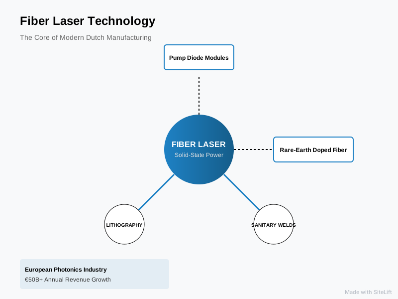
Infographic by SiteLift
How the Dutch High-Tech Manufacturing Ecosystem Leverages Fiber Lasers
The Dutch industrial manufacturing landscape differs markedly from high-volume automotive assembly hubs. Characterized by high-mix, low-volume, high-complexity production, the Dutch supply chain relies on fiber lasers to deliver precision, cleanliness, and adaptability across distinct sectors.
+-----------------------------------------------------------------------------------+
|               DUTCH HIGH-TECH & INDUSTRIAL FIBER LASER ECOSYSTEM                  |
+-----------------------------------------------------------------------------------+
|  [ Brainport Eindhoven ]   ===>  Precision optomechatronics, wafer handler tools, |
|                                  hermetic sensor encapsulation, ultra-low HAZ     |
|                                                                                   |
|  [ Agrifood Corridor ]     ===>  EHEDG-compliant food machinery, bacteria-free    |
|                                  weld seams, crevice-free stainless steel tanks   |
|                                                                                   |
|  [ Maritime & Offshore ]   ===>  Automated robotic gantry cutting, heavy-section  |
|                                  naval steel welding, subsea hydraulic piping     |
+-----------------------------------------------------------------------------------+
Brainport Eindhoven & Semiconductor Equipment Manufacturing
The technological cluster around Brainport Eindhoven forms the core of the Netherlands’ advanced mechatronics sector. Here, tier-one and tier-two suppliers build lithography modules, electron microscopes, and advanced wafer-handling equipment.
In this environment, mechanical tolerances are measured in single microns, and thermal stress during fabrication must be kept to a minimum. Machine shops use fine-tuned single-mode fiber lasers to profile structural parts made from Invar, titanium, and high-purity aluminium.
Sensors, actuators, and linear drive stages built for high-vacuum cleanroom duty are routinely joined using continuous-wave fiber lasers. Because fiber welding can be done without chemical fluxes and under inert shielding gas, assemblies remain free of organic residues that could cause outgassing in high-vacuum environments.
Agrifood Machinery and Stainless Steel Fabrication
The Netherlands is one of the world’s largest agricultural and food technology exporters. Stainless steel equipment manufactured throughout Gelderland, Overijssel, and Noord-Brabant must meet stringent European Hygienic Engineering & Design Group (EHEDG) directives.
EHEDG standards require that food-contact metal surfaces be free of crevices, micro-pores, and slag inclusions where bacterial colonies, such as Listeria, can settle.
Fiber laser cutting with clean nitrogen gas produces square, dross-free edges on AISI 304 and 316L stainless steel sheet. Furthermore, automated fiber seam welding creates smooth, rounded weld caps that require minimal mechanical grinding and polishing. This simplifies the post-treatment pickling and passivation steps needed to restore corrosion resistance.
Maritime and Heavy Industrial Fabrication across Rotterdam and Northern Yards
From mega-yacht construction in Zuid-Holland to naval patrol vessel fabrication and commercial shipbuilding in Groningen and Friesland, the Dutch maritime sector handles demanding structural tasks daily.
Shipyards use multi-kilowatt fiber lasers (ranging from 12 kW to 30 kW) mounted on large gantry tables to bevel, profile, and cut high-yield naval structural steel plates (such as DH36 and EH36).
The narrow kerf and minimal distortion of fiber cutting allow shipbuilders to fabricate large hull sections that fit together cleanly during dry-dock assembly. In offshore wind and dredging fabrication, heavy-duty fiber sources cut thick wall tubular sections, robotic pipe penetrations, and wear-resistant duplex steel subsea manifolds.
Best Practices for Fiber Laser Maintenance and System Longevity
Although an all-fiber architecture eliminates the optical mirrors of older laser designs, the high optical power densities inside these systems require disciplined handling. Effective fiber laser maintenance preserves beam quality and protects against expensive shop-floor downtime.
       OPTICAL CONTAMINATION PROFILE & FAILURE PATH

       Microscopic Dust Particle Landing on Window
                          |
                          v
       Absorbs 1070 nm Laser Light Energy
                          |
                          v
       Rapid Localized Heating (> 1000°C)
                          |
                          v
       Thermal Lensing (Focal Shift & Cut Drift)
                          |
                          v
       Substrate Cracking / Anti-Reflective Coating Burn-Through
Chiller Water Quality and Thermal Regulation
Because fiber laser sources operate with high efficiency, water chillers can be compact, but their precise control remains critical. Most modern sources use a dual-circuit chiller:
- The Low-Temperature Circuit: Cools the internal diode pump modules and optical fiber baseplates (typically set around 22°C to 24°C).
- The High-Temperature Circuit: Keeps the external delivery optical connector (QBH, Qplus, or QD) and cutting head optics slightly above ambient temperature (typically 28°C to 30°C).
Maintaining the delivery head slightly above ambient temperature prevents atmospheric moisture from condensing onto optical windows. In humid coastal environments, condensation on an optical surface will instantly absorb laser light and destroy the glass substrate.
Cooling water must be maintained at a neutral conductivity using specialized deionizing resin cartridges, with non-glycol, biocidal additives that prevent bacterial fouling within the internal cooling channels.
Protective Window Inspection and Contamination Control
The most vulnerable components in any industrial fiber laser are the protective cover glasses (cover slides) in the cutting or welding head. These sacrificial windows shield the focusing lenses from metal spatters and assist gas debris.
According to research by the Laser Institute of America, optical contamination on protective covers accounts for over 60% of premature cutting head failures in metal fabrication. Even a single 10-micron dust particle resting on an anti-reflective coating can absorb localized 1-micron radiation. This absorption causes thermal lensing—a dynamic shift in the focal plane that leads to edge burrs and poor cut quality—and can ultimately fracture the glass.
    COVER SLIDE INSPECTION CHECKLIST

    [ ] Step 1: Wipe down external cutting head exterior with lint-free alcohol cloth.
    [ ] Step 2: Establish a clean airflow environment (HEPA bench or still room).
    [ ] Step 3: Remove optical slide cartridge using powder-free nitrile gloves.
    [ ] Step 4: Illuminate the glass obliquely using a darkfield green LED inspection light.
    [ ] Step 5: If dust is present, blow clean using dry, oil-free canned nitrogen.
    [ ] Step 6: If residue remains, perform a single-pass drag wipe with lens tissue and
                spectroscopic-grade isopropyl alcohol (IPA).
    [ ] Step 7: Re-seat cartridge with fresh seal ring; never reuse a damaged O-ring.
Beam Delivery Cable Handling and Optical Connector Care
The beam delivery cable—terminated with a standardized connector like a QBH or QD plug—houses the silica glass guide that channels kilowatts of optical energy. Mechanics and operators must treat this cable with great care.
Pro Tip: Never twist or loop an optical delivery cable tighter than its rated minimum bending radius (typically 150 mm dynamic, 100 mm static). Bending the cable too sharply causes optical leakage from the cladding into internal dump layers, which can trigger emergency interlock shutdowns or permanently burn the protective armor jacket.
When disconnecting or seating the fiber into a processing head, operators should wear powder-free nitrile gloves in a cleanroom or clean bench setting. A microscopic contaminant on the entry face of the connector quartz block can back-reflect light into the diode modules, damaging the core source.
Key Takeaways
The table below summarizes the core mechanical and operational parameters of industrial fiber laser technology:
| Focus Area | Operational Parameter | Practical Engineering Consideration |
|---|---|---|
| Active Gain Medium | Ytterbium-doped silica fiber | Emits at 1030–1080 nm; lower quantum defect and high absorption in engineering metals. |
| Resonator Structure | Integrated Fiber Bragg Gratings (FBG) | Monolithic design; eliminates free-space mirrors, external optical cavities, and mechanical realignment. |
| Energy Consumption | 35% – 50% wall-plug efficiency | Lowers operating power draw and reduces the sizing and cost of external water chillers. |
| Beam Quality ($M^2$) | Single-mode ($M^2 < 1.3$) vs Multi-mode ($M^2 > 2.0$) | Small cores cut thin materials and foil quickly; larger cores improve thick-plate cutting and deep-weld stability. |
| Dutch Applications | Mechatronics, Food Processing, Marine | Clean cuts for cleanroom assemblies, smooth EHEDG-grade sanitary welds, and high-yield plate processing. |
| Primary Failure Point | Contaminated protective cover slides | Requires strict clean-bench handling protocols to avoid thermal lensing and catastrophic head damage. |
Why Monolithic Design Is the Most Underrated Advance in Industrial Photonics
When engineers evaluate machine tools, they often focus on peak power numbers. In trade show halls, banners promote 30 kW, 40 kW, and even 60 kW fiber laser sources.
However, focusing solely on high wattage misses the real reason fiber lasers disrupted manufacturing: their monolithic optical architecture.
In conventional solid-state and gas lasers, an optical cavity relies on carefully aligned mechanical components. These assemblies depend on kinematic mounts, elastomer seals, mirrors, and active cavity stabilization. In a busy production environment, that mechanical complexity creates vulnerability. Ambient temperature shifts in unheated warehouses cause focal drift, and vibrations from nearby 200-ton stamping presses gradually knock beam cavities out of alignment.
A fiber laser source bypasses those issues entirely. By fusing the pump diodes, the combiner, the active doped core, the Fiber Bragg Gratings, and the beam delivery cable into a single unbroken strand of glass, the resonator eliminates all mechanical adjustments.
   TRADITIONAL FREE-SPACE RESONATOR              MONOLITHIC FIBER RESONATOR

       [Mirror]   [Gas / Crystal]   [Mirror]         [HR-FBG]=====[Active Core]=====[OC-FBG]
          |              |             |                 Fused Silica Solid Glass Path
       (Vibration- & Dust-Prone Cavity)                   (No Free Optics, No Realignment)
This all-fiber construction changes the laser source from a delicate laboratory instrument into a true shop-floor utility, much like an electric motor or hydraulic pump. For Dutch manufacturers operating high-mix, low-volume shifts with lean operational teams, that reliability is invaluable. High laser power is useful, but day-in, day-out reliability is what actually keeps shop floors profitable.
The true genius of the fiber laser is not simply that it emits a powerful beam of light, but that it turns delicate optical physics into a dependable, solid-state machine tool component.
— tlsbv.nl
Integrating Fiber Laser Solutions into Your Manufacturing Floor
Selecting the right optical parameters requires balancing raw source power with your specific workpiece materials, part geometries, and production volumes. Whether you are integrating automated wobble heads for structural aluminium fabrications, looking to reduce thermal distortion on thin-gauge stainless steel food equipment, or designing an automated laser workstation for precision electronics, matching core diameters and pulse structures to your process is critical.
At Te Lintelo Systems (TLS), we have spent decades supporting the high-tech, industrial, and scientific communities across the Netherlands and broader Europe. Established in 1985, TLS provides optical design guidance, components, and complete laser solutions from top photonics manufacturers worldwide.
If you are developing a new laser system or upgrading an existing process line, our team of technical specialists can help you review your optical path, evaluate beam quality requirements, and choose the right laser engine for your factory.
FAQ
What is the difference between a fiber laser and a CO2 laser?
A fiber laser generates light inside a solid silica glass fiber doped with rare-earth ions (typically ytterbium) and emits at a wavelength of roughly 1.07 microns. A $CO_2$ laser uses an electrical discharge to excite a gas mixture of carbon dioxide, nitrogen, and helium, producing light at 10.6 microns. Fiber lasers operate with roughly three to four times the wall-plug efficiency of $CO_2$ systems, need no laser gases or resonator mirrors, and their 1-micron light is absorbed far more readily by non-ferrous metals like copper, brass, and aluminium.
Why are ytterbium fiber lasers preferred for metal processing?
Ytterbium fiber lasers are the standard choice for metal cutting and welding because their 1030 nm to 1080 nm emission wavelength is well-absorbed by most engineering metals. Furthermore, ytterbium ions have a small quantum defect—the energy lost as heat between optical pumping and laser emission is minimal. This low heat generation allows manufacturers to scale up optical output power reliably without creating severe thermal distortions inside the fiber core.
Can a fiber laser cut highly reflective metals like copper and brass?
Yes. Although copper, bronze, and brass reflect 10.6-micron $CO_2$ laser light heavily, their absorption increases significantly at the 1.07-micron wavelength of fiber lasers. Modern industrial fiber sources are also equipped with multi-stage back-reflection isolators. These devices detect and safely divert light bouncing straight back from the melt pool into an internal water-cooled beam dump, protecting the optical cavity from damage during piercing.
What maintenance routines are required for an industrial fiber laser source?
Because the internal fiber source is completely sealed, it requires no internal mirror alignment or gas refills. Regular maintenance focuses on external optical and environmental elements:
- Inspecting, cleaning, and periodically changing the protective cover slide in the cutting or welding head.
- Checking cooling water condition, including monitoring electrical conductivity, changing deionizing filter cartridges, and replenishing biocides.
- Checking delivery cable bend radii and cleaning optical connectors (like QBH connectors) in a clean bench environment whenever they are relocated.
How does fiber laser technology support the Dutch high-tech supply chain?
The Dutch manufacturing ecosystem relies on high-mix, low-volume, precision manufacturing. In Brainport Eindhoven, fiber lasers cut and hermetically weld ultra-clean structural components for lithography tools and electron microscopes with minimal Heat-Affected Zones and zero flux residues. In the Dutch agrifood equipment sector, fiber systems produce the flat, smooth, dross-free cuts and clean welds required to meet EHEDG sanitary standards.